Table of Contents
Solar panel clamp profiles should be selected around the complete assembly, with the controlling interfaces agreed before an order is released. The relevant product role is to hold a photovoltaic module at approved frame locations. For the buyer, the first decision is how the proposed component will meet that role in the actual equipment or installation. A nominal size or an attractive product image is useful context, but it does not resolve the fit, material and acceptance requirements.
This guide focuses on module height and clamp selection. The review needs to cover module frame height, clamp engagement, fastener reach and mounting zones. The practical risk is that a clamp may bottom out on its rail before developing the intended grip on the frame. Addressing that mechanism early makes quotations easier to compare and gives the sample review a clear purpose.
A review scenario for solar panel clamp profiles
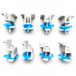
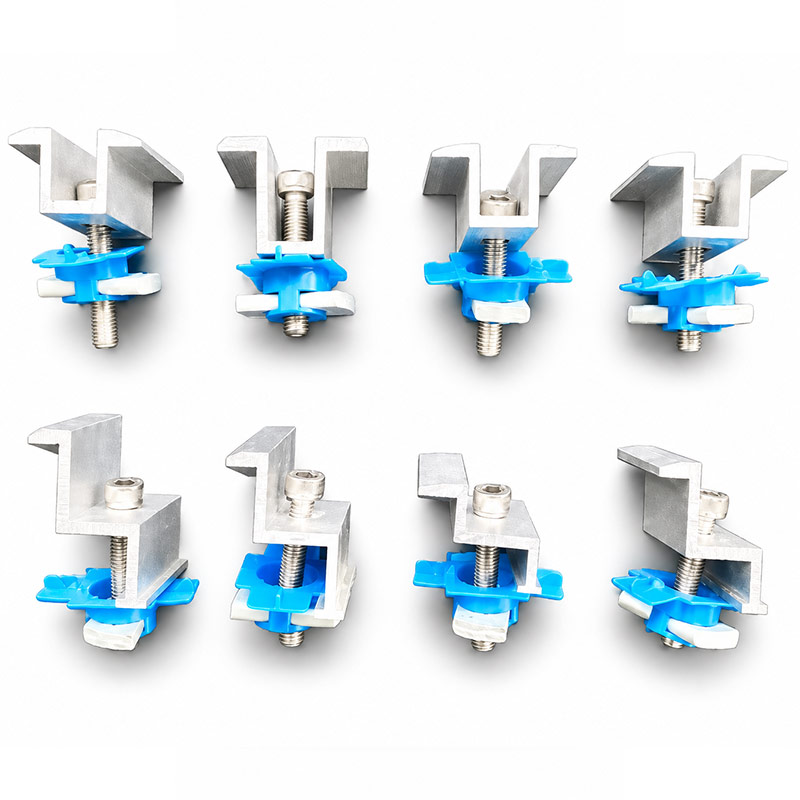
Trial a mid clamp between two real module frames. Include the end clamp at a row boundary because the stack and fastener engagement differ.
For solar panel clamp profiles, turn the comparison into a written decision record. List the proposed configuration and the alternative, then compare module frame height, clamp engagement, fastener reach and mounting zones under the actual application conditions. Ask which requirements are already demonstrated and which still need a drawing review, a calculation or a sample trial. This keeps the choice tied to evidence rather than to a familiar product name.
Match clamps to the module installation requirements
Solar module clamping requirements belong to the specific module system. For solar panel clamp profiles, obtain the module manufacturer’s permitted mounting zones, frame details and installation instructions. Confirm that the clamp grips the intended region without interfering with glass, drainage or frame features. A stated module height range is a fit input rather than universal evidence of module compatibility.
A solar panel clamp profiles trial should include the real module frame, rail, clamp and fastener stack. Check engagement and clearances at both mid and end positions where those details differ. Apply the specified assembly procedure for the selected hardware. Do not derive a new torque value from the profile thickness. If the module model changes, revisit the clamping detail even when its nominal overall dimensions look similar.
Use the actual hardware envelope
Operating hardware for solar panel clamp profiles has a dimensional envelope and a permitted application range. Record hinge, roller, lock or connector models alongside the frame drawing. Verify the fastener engagement and clearance needed for adjustment and servicing. A generic hardware groove is not a guarantee that every fitting marketed for a similar system will work.
For solar panel clamp profiles, test the intended assembly with production-representative hardware and the proposed panel mass or service condition. Check access after neighboring parts are installed. Keep hardware substitutions controlled, including seemingly minor changes in screw head or washer geometry. A change can affect clearances, contact area and operating position even if the replacement has the same nominal fastening size.
Control drawing and process changes
A repeat order for solar panel clamp profiles should begin by confirming the current drawing and sample references. Small changes in hole position, coating, gasket or material condition can affect an established interface. Use a revision log that describes the changed features and identifies the approval authority. Avoid relying on a new file name or a message that says to use the latest version.
For solar panel clamp profiles, review work in progress when a change is released. Decide whether existing parts remain acceptable, require rework or must be segregated. Update inspection fixtures and packing labels along with the manufacturing drawing. A supplier can produce the new geometry correctly and still ship a mixed revision if inventory controls are overlooked. Keep the final agreement attached to the purchase order and batch release record.
Include anodizing in the dimensional plan
Anodizing affects the finished surface and can influence the fit of solar panel clamp profiles at narrow grooves, threads and close-clearance interfaces. Mark functional areas that need masking or a controlled finished dimension. Agree appearance and process requirements before approving the die or machining route, since reworking a finished part can expose bare metal or create a visible mismatch.
A sample of solar panel clamp profiles should represent the same alloy, pretreatment and anodizing route planned for production. Differences in material or surface preparation can alter appearance even when the nominal color is unchanged. State any required coating inspection and the acceptance location. Do not infer outdoor service life from appearance alone or apply a coating report from an unrelated system to the current order.
Preserve specified electrical continuity details
Some photovoltaic assemblies using solar panel clamp profiles require a defined bonding and grounding arrangement. Coatings, fasteners and contact details can influence electrical continuity. The electrical designer and equipment documentation should identify the approved method. A mechanical fit trial alone does not prove that the assembled rack satisfies the required electrical function.
For solar panel clamp profiles, keep any listed or specified bonding hardware identified in the bill of materials. Do not replace it with an ordinary washer solely because it fits the same bolt. Similarly, isolating details introduced to address dissimilar-metal contact need review against the electrical design. Inspection should verify the specified components and assembly method, with electrical testing performed where required by the approved project procedure.
Design corner joints as part of the frame
Corner quality in solar panel clamp profiles depends on end preparation, connector engagement, fasteners and frame geometry. A neatly cut miter can still open if the connector lacks adequate bearing or the frame is forced out of square during installation. Show the joint detail and assembly sequence on the drawing. Include any adhesive, sealant or gasket that forms part of the intended connection.
A sample of solar panel clamp profiles should include a complete corner with the production finish. Measure diagonals and check the visible joint after assembly and any agreed operating trial. Keep decorative gap acceptance separate from structural or sealing requirements. If the connector changes, review the joint again rather than assuming that a component with similar external dimensions provides equivalent engagement.
Pack long finished members to preserve geometry
Long lengths of solar panel clamp profiles can be scratched, bent or twisted during transport if bundles and supports are poorly arranged. Define separators, bundle restraint and the support needed for the actual length and section. Keep visible surfaces from rubbing against bare metal or contaminated packing. Packaging should also prevent small hardware or cut pieces from moving into finished faces.
For solar panel clamp profiles, label part numbers, lengths, finish batches and orientation where relevant. Distinguish an approved packing plan from a claim that transport damage is impossible. Receiving inspection should examine the bundle condition before unpacking and record any deformation or impact marks. Retain packaging photographs when a claim is raised, since they can help establish whether damage occurred in production, packing or handling.
Locate and validate splices deliberately
A transport-length member of solar panel clamp profiles may need a splice, but a splice is a connection detail with its own force-transfer and movement requirements. Identify its position relative to supports and loads. Show connector overlap, fasteners and the section orientation. Two pieces joined into a straight line are not automatically equivalent to one continuous extrusion.
For solar panel clamp profiles, the designer should define the permitted splice arrangement and any required validation. Inspect the holes and mating fit using the production connector. Include installation access and identification so the correct detail is used on site. If the shipping length changes, review the splice plan before cutting stock. A transport decision can otherwise create an unreviewed structural change in the final assembly.
Evidence to compare for solar panel clamp profiles
| Decision | Incomplete basis | Evidence to request |
|---|---|---|
| Assembly interface | A nominal size or photograph | module frame height, clamp engagement, fastener reach and mounting zones |
| Material and finish | A generic material name | Specified alloy or grade, condition and finish route |
| Sample release | Appearance alone | module installation manual, clamp cross-section and assembled stack measurement |
| Commercial comparison | Unit price without exclusions | Included processing, documents, packing and delivery basis |
The comparison is intended to guide a review of solar panel clamp profiles, not to supply a universal design value. Choose the acceptance basis from the actual project and keep it consistent across quotation, sample approval and receiving inspection. If the complete assembly needs performance validation, define that work separately from the supplier’s component measurements.
Request a review of solar panel clamp profiles
Beihaoli lists Solar Panel Clamp Profiles in its catalogue. Use that page to explain the product family, then send the current drawing and application requirements for a configuration-specific review. For solar panel clamp profiles, highlight module frame height, clamp engagement, fastener reach and mounting zones and include the evidence required for acceptance. Catalogue descriptions and photographs should not be treated as an order-specific capacity or certification statement.
The company’s manufacturing capabilities page describes forging, extrusion, machining, finishing and inspection support. Ask which operations and documents are included in the proposed solar panel clamp profiles supply route. Provide the required quantity, sample expectations and delivery destination so the response can address tooling, first-article work, packing and shipment planning on the same technical basis.
For independent background, consult the U.S. Department of Energy photovoltaic system design overview. Use this overview for system context. Project-specific structural, module and electrical requirements still need their own evidence.
Questions about solar panel clamp profiles
What information is needed to specify solar panel clamp profiles?
Provide the application, current drawing, material and supplied condition, dimensions, finish and quantity. For this interface, identify module frame height, clamp engagement, fastener reach and mounting zones. Include the mating parts so fit is reviewed as an assembly.
Can solar panel clamp profiles be selected by appearance alone?
No. A photograph helps explain the shape but cannot establish tolerances, material, service limits or system qualification. In this application, a clamp may bottom out on its rail before developing the intended grip on the frame. Request the relevant drawing and evidence.
Which evidence should accompany solar panel clamp profiles?
Agree an inspection package before ordering. Relevant inputs include module installation manual, clamp cross-section and assembled stack measurement. Material records and assembly trials answer different questions, so neither should be used as a substitute for the other.
When should buyers request a sample of solar panel clamp profiles?
Request a sample before batch release when a new interface, finish, tool or material is involved. Define the checks in advance and retain the accepted sample identity and drawing revision.
What should a quotation for solar panel clamp profiles include?
Ask for the supplied condition, included processing and inspection, packaging, quantity basis and order-specific delivery plan. Have deviations and exclusions listed explicitly so competing offers can be compared on the same scope.