Table of Contents
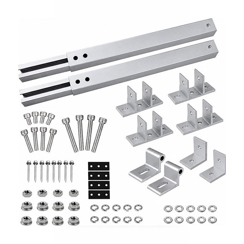
Solar bracket connector profiles should be selected around the complete assembly, with the controlling interfaces agreed before an order is released. The relevant product role is to join solar rack beams, columns and inclined members. For the buyer, the first decision is how the proposed component will meet that role in the actual equipment or installation. A nominal size or an attractive product image is useful context, but it does not resolve the fit, material and acceptance requirements.
This guide focuses on connection layout selection. The review needs to cover slot width, bolt bearing area, bracket angle and tool clearance. The practical risk is that an oversized slot or an eccentric connection can permit slip despite an apparently tight fastener. Addressing that mechanism early makes quotations easier to compare and gives the sample review a clear purpose.
A review scenario for solar bracket connector profiles
Prepare one joint with all mating parts, including washers and the selected finish. Compare the intended load path with a joint assembled using a thinner substitute connector.
For solar bracket connector profiles, turn the comparison into a written decision record. List the proposed configuration and the alternative, then compare slot width, bolt bearing area, bracket angle and tool clearance under the actual application conditions. Ask which requirements are already demonstrated and which still need a drawing review, a calculation or a sample trial. This keeps the choice tied to evidence rather than to a familiar product name.
Inspect grooves with the real mating hardware
A groove in solar bracket connector profiles performs a specific job, such as retaining a gasket, panel, spline, fastener or connector. Width alone does not describe that job. Depth, lip shape, entry clearance and the surrounding wall all influence engagement. Identify the mating component and its tolerance on the drawing so the extrusion supplier can review the complete fit.
For solar bracket connector profiles, combine dimensional inspection with an agreed functional trial using production-representative hardware. A hand-selected fastener that happens to fit is weak evidence for a batch. Include finish allowance and the range of mating sizes. Where the joint transfers load, a fit check establishes assembly compatibility only; any required load or slip validation should follow the approved design and test plan.
Review the solar rack load path
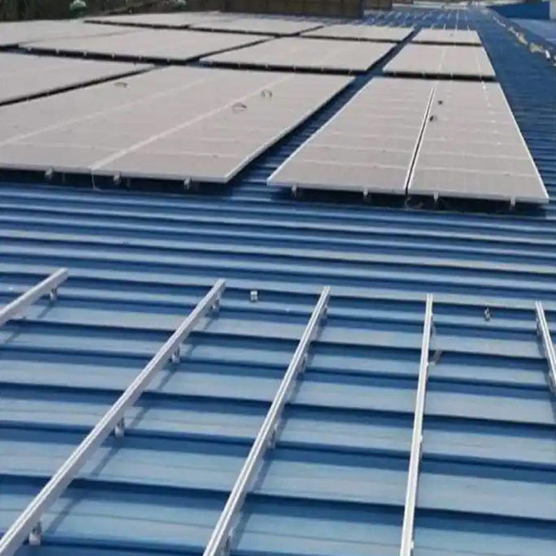
In a solar mounting application, solar bracket connector profiles are part of a load path running from the module through clamps, rails, connections and supports to the foundation or roof. The project designer must consider the site actions and combinations required for that installation. A profile supplier’s catalogue description does not establish the capacity of every possible rack layout.
For solar bracket connector profiles, provide the module arrangement, support spacing, orientation and connection details with the inquiry. Identify whether the section is continuous or spliced. Review changes in tilt, height and roof zone as project changes. Keep the approved calculation and assembly drawing linked to the supplied parts so an installer does not extend a span or move a support based only on the apparent stiffness of the extrusion.
Assign tight tolerances to functional features
Tolerances for solar bracket connector profiles should follow the function and manufacturing route. Identify the dimensions that control fit, sealing, movement or load transfer, then consider how their variation accumulates with the mating parts. Tightening every dimension can increase cost while leaving the important stack unresolved. A clear datum scheme and a few justified critical limits are often more useful than a drawing filled with unexplained precision.
For solar bracket connector profiles, agree the measurement method and final processing state for each critical feature. A dimension measured before coating or in a fixture may not represent its delivered condition. Review the complete stack with the buyer’s parts and document any assumptions. If the required tolerance cannot be achieved economically through the original route, compare a design adjustment with a targeted secondary operation before changing the entire specification.
Control cut length, squareness and end condition
Cut-to-length solar bracket connector profiles parts need an agreed datum, length tolerance and end condition. A correct length measured along one edge can hide an out-of-square cut that opens a visible corner or shifts a connector. Identify whether the finished length includes end machining or inserted components. The saw process and subsequent deburring should preserve the feature used to locate the assembly.
For solar bracket connector profiles, inspect representative pieces from the production setup and check the first assembled joint. Protect cut ends from dents during handling, especially where the end is visible or forms a sealing interface. If different lengths are packed together, use clear part labels. Re-cutting an incorrectly identified piece on site can remove a required hole, change an end detail or leave the finish edge unprotected.
Approve a representative full assembly
Small swatches and short samples are useful, but they cannot show every interaction in solar bracket connector profiles. Choose a mock-up that includes the critical span, corner, infill, hardware and finishing detail. Define the trial objective before building it. A sample intended to approve color should not silently become the only evidence for movement, load or sealing performance.
For solar bracket connector profiles, record the exact components and drawing revision used in the mock-up. Photograph relevant details and retain measurements for the critical interfaces. If production uses a different gasket, fastener or alloy, review the effect on the accepted assembly. This keeps sample approval useful throughout the order and prevents a visually similar prototype from concealing changes that affect function.
Allow for movement at the installation interfaces
Temperature changes and neighboring materials can create relative movement around solar bracket connector profiles. Identify the installation length, restraint locations, adjoining materials and expected exposure. The responsible designer should specify where movement is permitted and how joints or fixings accommodate it. A long member rigidly restrained at every point can behave differently from a short approval sample.
For solar bracket connector profiles, show movement gaps and fixing details on the assembly drawing rather than leaving them to the installer. Check that sealants, trim and hardware do not unintentionally bridge a designed gap. If the installation length changes, review the detail again. The objective is to maintain fit and function through the expected service conditions, with evidence appropriate to the complete system.
Choose a section from the assembly requirements
The best starting point for solar bracket connector profiles are the assembled function rather than the heaviest-looking cross-section. Identify the supported load, span, mating parts, movement and installation envelope. Then compare candidate sections for the actual orientation and connections. A profile that looks substantial in a photograph may place material where it contributes little to the required stiffness or interferes with a neighboring component.
For solar bracket connector profiles, obtain a dimensioned section drawing and identify the features that determine fit. Include internal cavities, grooves and the available wall around fasteners. If a catalogue section is modified, review whether the new feature can be extruded directly or requires secondary machining. Keep the extrusion envelope separate from finished-part details so the quotation covers the complete component rather than only the raw length.
Measure straightness and twist over useful lengths
Straightness and twist influence how solar bracket connector profiles assembles over its full working length. A short cut sample can look excellent while a long member produces a visible gap, a binding track or an uneven joint. State the measurement length and support condition, and distinguish local variation from full-length deviation. Use the project-required tolerance basis instead of an informal statement that the profile should be straight.
An inspection of solar bracket connector profiles should include the delivered length and the orientation relevant to installation. If parts are cut from longer stock, identify whether the requirement applies before cutting or after secondary operations. Holes, slots, heat exposure and asymmetric machining can change the final shape. Compare the finished part with the accepted sample using the same method so manufacturing and receiving teams are not measuring different conditions.
Evidence to compare for solar bracket connector profiles
| Decision | Incomplete basis | Evidence to request |
|---|---|---|
| Assembly interface | A nominal size or photograph | slot width, bolt bearing area, bracket angle and tool clearance |
| Material and finish | A generic material name | Specified alloy or grade, condition and finish route |
| Sample release | Appearance alone | assembled joint drawing, connection calculation and sample fit record |
| Commercial comparison | Unit price without exclusions | Included processing, documents, packing and delivery basis |
The comparison is intended to guide a review of solar bracket connector profiles, not to supply a universal design value. Choose the acceptance basis from the actual project and keep it consistent across quotation, sample approval and receiving inspection. If the complete assembly needs performance validation, define that work separately from the supplier’s component measurements.
Request a review of solar bracket connector profiles
Beihaoli lists Solar Bracket Connector Profiles in its catalogue. Use that page to explain the product family, then send the current drawing and application requirements for a configuration-specific review. For solar bracket connector profiles, highlight slot width, bolt bearing area, bracket angle and tool clearance and include the evidence required for acceptance. Catalogue descriptions and photographs should not be treated as an order-specific capacity or certification statement.
The company’s manufacturing capabilities page describes forging, extrusion, machining, finishing and inspection support. Ask which operations and documents are included in the proposed solar bracket connector profiles supply route. Provide the required quantity, sample expectations and delivery destination so the response can address tooling, first-article work, packing and shipment planning on the same technical basis.
For independent background, consult the U.S. Department of Energy photovoltaic system design overview. Use this overview for system context. Project-specific structural, module and electrical requirements still need their own evidence.
Questions about solar bracket connector profiles
What information is needed to specify solar bracket connector profiles?
Provide the application, current drawing, material and supplied condition, dimensions, finish and quantity. For this interface, identify slot width, bolt bearing area, bracket angle and tool clearance. Include the mating parts so fit is reviewed as an assembly.
Can solar bracket connector profiles be selected by appearance alone?
No. A photograph helps explain the shape but cannot establish tolerances, material, service limits or system qualification. In this application, an oversized slot or an eccentric connection can permit slip despite an apparently tight fastener. Request the relevant drawing and evidence.
Which evidence should accompany solar bracket connector profiles?
Agree an inspection package before ordering. Relevant inputs include assembled joint drawing, connection calculation and sample fit record. Material records and assembly trials answer different questions, so neither should be used as a substitute for the other.
When should buyers request a sample of solar bracket connector profiles?
Request a sample before batch release when a new interface, finish, tool or material is involved. Define the checks in advance and retain the accepted sample identity and drawing revision.
What should a quotation for solar bracket connector profiles include?
Ask for the supplied condition, included processing and inspection, packaging, quantity basis and order-specific delivery plan. Have deviations and exclusions listed explicitly so competing offers can be compared on the same scope.